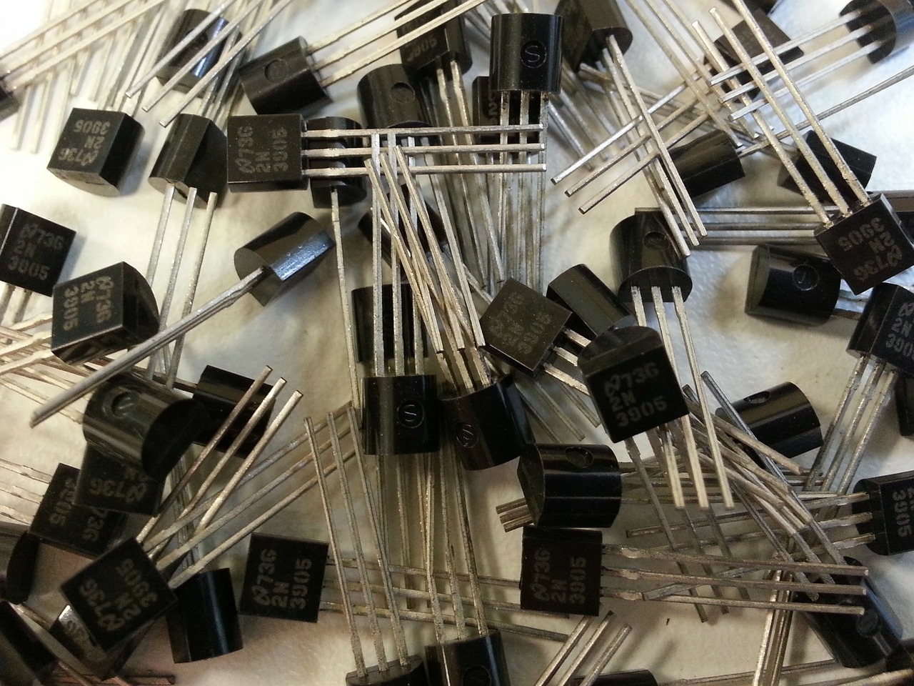
Making computers possible, transistors were invented in 1947. They are used as switches and amplifiers in circuits and are key to controlling flow of current.

Structure
The most common type of transistor is the bipolar transitor, often an NPN transitor, with a circuit diagram like this:
 The b stands for base, c for collector and e for emitter.
A small current flowing between the base and emitter allows for a flow of current between the collector and emitter. The flow of current from the base effectively acts as a switch to turn on the main circuit. The transistor is made of semiconducting material, silicon. PNP transistors also work in a very similar way.
N-P-N junction
Like an LED, transistors are made of P and N type silicon. The p-type is doped with impurities such as boron and aluminium which gives it a lack of electrons. Silicon doped with phosphorus or arsenic, for example, has an abundance of conduction electrons and is named n-type.
However, the difference between a transistor and LED is that the transistor has 3 layers of P and N type silicon, giving it the N-P-N structure:

The junction between the base to the emitter is forward-biased as current flows from positive to negative (opposite to electron flow). A small current from base therefore travels to the emitter. The electons fill the holes in the P-type semiconductor.
The junction from collector to base is reverse-biased so the current cannot flow. However, when a current is flowing from the base, this is possible as holes in the P-type are filled and the current can now in the main circuit.
Logic Gates
Combinations of transistors can be used in logic gates to create logic circuits. The two most common are the AND and OR gates. They use binary so 0 is off and 1 is on. 0 will correspond to very low or zero current and 1 will be a higher current.
AND gate
The output of an AND gate is 1 only if all the inputs also have a value of 1. An AND gate is made by connecting transistors in series:

OR gate
The output of an OR gate will be 1 when one or more of the inputs is 1. The transistors in this case are still arranged in series but additional connections to the output means that only one of the transistors has to have an output:

References
http://www.explainthatstuff.com/howtransistorswork.html
https://physics.info/semiconductors/
http://www.bbc.co.uk/schools/gcsebitesize/design/electronics/switchesrev3.shtml